
MODULAR EVAPORATOR UNIT AND LRW CEMENTING PLANT
NEW TYPE OF INSTALLATIONS FOR DISTILLATION AND CONCENTRATION
Problems in the formation of deposits on heat transfer surfaces during evaporation and distillation of solutions exist in various industries (nuclear, chemical, hydrometallurgical, pharmaceutical, food, etc.). The proposed technology is aimed at solving this problem and creating equipment for concentrating and distilling solutions without the use of chemical reagents. In combination with the use of technology Mechanical Vapor Recompression (MVR) provides an energy-saving mode of operation and low operating costs. The implementation of the principle of continuous mechanical cleaning of heating surfaces during the evaporation of the solution allows an unlimited increase in the interval between flushing of the evaporating equipment
Reagentless technology evaporation and distillation
One of the prototypes of film-type drum-type evaporators is a drumtype crystallizer in which the problem of surface incrustation is solved by placing inside a heavy chain that rubs against the surface as the drum rotates. In the proposed design, instead of the chain, it is proposed to use either a screw structure that, when rolled in a rotating drum, not only cleans the walls, but also moves the resulting sediments to the discharge site, or a set of scrapers that perform the same function.
Unloading the concentrate into a vacuum tank is carried out by periodically opening the solenoid valve on the concentrate discharge line from the drum. Under the effect of a large pressure drop, the flow velocity in the pipeline is large enough, and the presence of crystal particles in the stream cleans the wall and does not allow the formation of deposits in the concentrate discharge pipeline.
The modular construction of the evaporator is proposed. This will reduce the cost of manufacturing equipment. In addition, the use of modularity has a number of other advantages:
• Easy scalability of the evaporator;
• Simple technology of manufacturing, assembly and transportation;
• Manufacturing of modules in large batches;
• Rapid adjustment of evaporation plants to different capacities, etc.
The evaporation plant consists of a horizontally rotating drum placed in a sealed housing. On the one hand, the working medium is fed into and out of the module, and on the other hand, there is a sealed rotary drive (for example, a magnetic clutch), which allows solving problems with the tightness of the evaporator module and the installation as a whole.
Application area:
Nuclear industry: processing (concentration) of liquid radioactive waste;
• Non-ferrous metallurgy: evaporation in hydrometallurgical technologies;
• Chemical and food industry: concentrating solutions of mineral and other salts, as well as alkalis;
• Pharmaceutical and food industry: production of concentrated liquid plant extracts and regeneration of the extractant;
• Washing and cleaning: regeneration of industrial water from washers;
• Galvanic production: galvanic solutions and washing water;
• Processing of toxic solutions and industrial wastewater, etc.
Prototypes

PRINCIPLE OF OPERATION
Thermal cleaning or evaporation (distillation) is currently one of the main methods for separating the solvent (most often water) from contaminated solutions, because:
• processing liquid waste of any degree of salt concentration;
• allows cleaning the solution of pollutants in any form (ionic, molecular, colloidal);
• low requirements for the quality of the evaporated solutions, which makes it possible to exclude the use of preliminary special sedimentation operations;
• provides a high cleaning ratio, which allows to completely solve the problem of cleaningthe solvent (for example, water) to the established norms.
Such advantages of the technology of cleaning solutions are not available in other methods. The most significant drawback of the thermal cleaning method is the high energy intensity. This shortcoming leads to the search for ways to implement this method, either on a cheap energy carrier or using the Mechanical Vapor Recompression (MVR) technology
PRINCIPLE OF OPERATION on the proposed technology for the physics of the process is most similar to rotary evaporators, but the flow of material flows is continuous, without the need for periodic filling of the evaporation vessel and complete drainage of the concentrate. In addition, there is a mechanical system for cleaning the heating wall from deposits under the level of the solution to be evaporated, which became possible when changing from the shape of the bulb to the shape of a hollow cylinder
As in rotary evaporators, the principle of the action of drum film evaporators (DFE) is based on the evaporation of a solvent (for example, water) from the surface of a liquid film spreading along the internal heated surface of a rotating drum. The difference from the operation of rotary evaporators is the method of heating the evaporation vessel. If in a rotary evaporator the glass bulb heats when it is partially submerged in a bowl of heated water or oil, condensing steam is used in the DFE to heat the evaporative drum on the outer surface.
Cleaning of the heating surface of the drum from salt deposits is performed mechanically, under the level of solution, for example, when using scraper elements, or rolling with a spiral auger when the drum rotates.
The process of film evaporation in a rotating vessel either eliminates or reduces the fragmentation of the solution many times as a result of rupture of vapor bubble films and entrainment of small droplets (aerosols) together with steam into the condenser, which provides a high degree of purification of the condensate of the secondary vapor from contaminants.
Evaluation of the efficiency of the technology of drum film evaporation
Competitive advantages
• Technological science-intensive approach, the production of unified evaporated modules is cheaper and their high quality is ensured;
• There are practically no limitations on the capacity of the evaporator, since the number of unified evaporator units involved is unlimited;
• Installation of evaporating modules in the unit can be carried out taking into account the existing geometry of allotted areas using simple lifting and transport equipment;
• Convenience of transportation, loading, unloading, installation and dismantling of unified modules;
• The technology of modular construction allows to shorten the terms of project realization as much as possible, and this equally concerns both the time of manufacturing of unified modules and the time of installation of evaporating plants;
• Universality — at any time you can purchase the necessary modules and solve the problem of increasing productivity;
• When steam recompression is used, recirculation of thermal energy ensures high process efficiency and eliminates the need for heating steam and cooling circuits;
• Drum film evaporator with a self-cleaning system ensures a continuous cycle of operation without degrading the heat transfer parameters;
• Automatic operation with a simple control and monitoring system;
• High degree of solution cleaning;
• Possibility of using an additional secondary cleaning system;
• Multifunctionality of the complex: distillation, extraction, concentration;
• Low staff qualification requirements;
• In the nuclear power industry, the dose loads on personnel are sharply reduced due to the lack of need for mechanical cleaning of the heat exchange tubes;
• High maintainability;
• Relatively low cost of devices and their installation;
• Low operating costs;
• Integration into the continuous technological cycle.
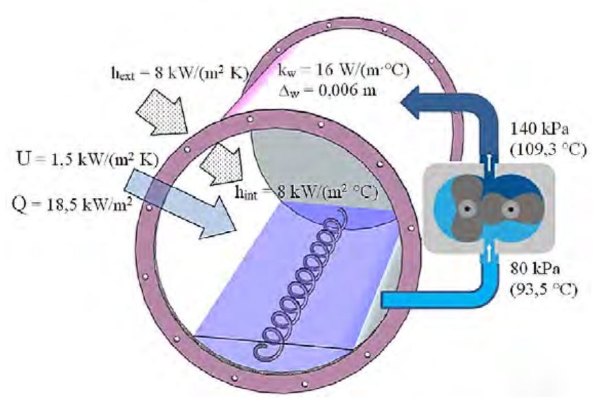
The efficiency of the technology of drum film evaporation is due to high coefficients of heat transfer during condensation (the outer wall of the drum) and during evaporation (the inner wall of the drum).
The efficiency of the technology of drum film evaporation is due to high coefficients of heat transfer during condensation (the outer wall of the drum) and during evaporation (the inner wall of the drum).
The use of MVR technology makes it possible to use secondary steam, obtained inside the drum, as a heating steam for the steam jacket of the same drum, which allows to reduce power consumption by several times as productivity increases.
The operating principle of the evaporator is quite simple. The evaporated solution through a recuperator with hot condensate is fed into a rotating evaporative drum, where it evaporates from the heated film. The resulting steam is compressed and heated in a Roots-type compressor, after which it is fed to the outer wall of the drum, where it is condensed and the hot condensate is transferred to the recuperator.
The electromagnetic valve is periodically opened and the concentrate comes from the drum to a low-pressure container, which can also serve as a measuring vessel.
To ensure the normal operation of the installation, it is necessary to have a compressed air system and a vacuum system. Due to the mechanical method of cleaning the heating surface from deposits, there are no restrictions on the degree of evaporation of saline solutions. Crystallization and precipitation of a part of salts into a solid sediment is not a problem, since during the rolling of a spiral auger or the operation of scrapers, solid particles move to the point of discharge, and do not accumulate at the bottom of the rotating drum.
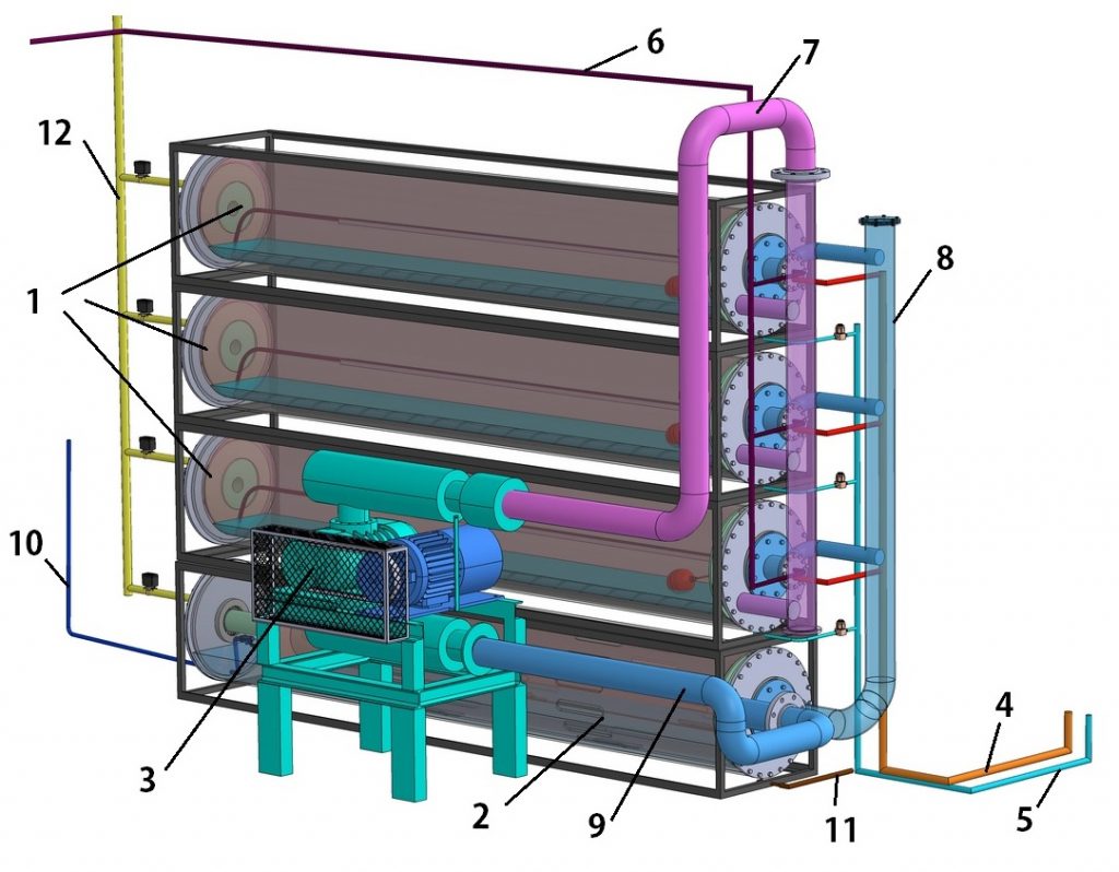
Технологическая схема модульной выпарной установки
All tanks (1, 5, 10) are connected through the shut-off valves to the compressed gas systems and vacuum systems (not shown in the diagram), which are connected periodically.
From the vessel under excessive pressure 1, the initial solution is fed and heated in the recuperator 2, and then the heated solution is sent to the drum film evaporators (DFE) 3 (red dashed line).
After reaching the required degree of concentration of the solution, the solenoid valve 4 is periodically opened and the concentrate enters the concentrate collection vessel 5 under vacuum.
Secondary steam 6 at a pressure of 0.08 MPa (blue solid line) is taken from the cavity of the drum 3 by the Roots 7 pump, in which it is mechanically compressed to a pressure of 0.15 MPa, and then the heated vapor 8 (green solid line) is fed into the heating jacket drum 3. On the outer surface of the drum, there is condensation of the heating steam and accumulation of condensate in the lower part of the heating jacket. Condensate (blue dashed line) through the steam trap 9 is directed to the heat exchanger 2, where it warms the initial solution. The cooled condensate is then fed to the condensate collection tank 10, which is under vacuum.
Excess gas pressure and vacuum are generated by the compressor and vacuum pump, not shown in the flow diagram.
Productivity per evaporated condensate of one module with a drum, in which the length of the heating surface is 5.0 m and the diameter is 0.5 m, is 0.25 m3 / h. The capacity of the entire plant is determined by the number of modules selected based on the performance of the selected vapor compression compressor.
The operation algorithm of the evaporator is extremely simple, and the regulation is based on the use of passive devices — float valves 11 that automatically maintain a predetermined level of filling of drums and thermodynamic steam traps 9 that open as condensation accumulates in the heating jacket body. It should be taken into account that the mass flow rate of generation of secondary vapor in all modules will be the same because of the identity of the evaporation area and the temperature difference (saturated vapor pressure) inside and outside the drum. Evaporation of the solvent leads to a decrease in the level, which is automatically compensated by the flow of solution entering the drum through the float valve 11.
Depending on the required degree of concentration of the solution, the frequency and duration of opening of the valve 4 is set, allowing the ready concentrate to be withdrawn to one of the vessels under vacuum 5 (the other vessel 5 is then released and ready to receive the concentrate). Duplication of the vessels of the initial solution, the vessels of collection of the concentrate and the vessels for collecting condensate allows to ensure the continuity of the process according to the scheme — one vessel is working, and the other is getting ready for work (this vessel is emptied or filled).
Advantages of the presented scheme are:
• Low power consumption;
• There is no need for a cooling water circuit and a source of heating steam;
• The ability to evaporate scale-forming solutions and solutions with the precipitation of crystals;
• Modularity of the evaporative unit;
• Absence of liquid pumps;
• Continuity of the evaporation process;
• Unlimited time cycle between washes to remove sediment;
• Passive principle of adjusting the level of solution in the evaporator drums of the modules;
• Passive principle of operation of steam traps, taking condensate from the modules;
• Minimum number of stop valves, etc.
Modular evaporator design
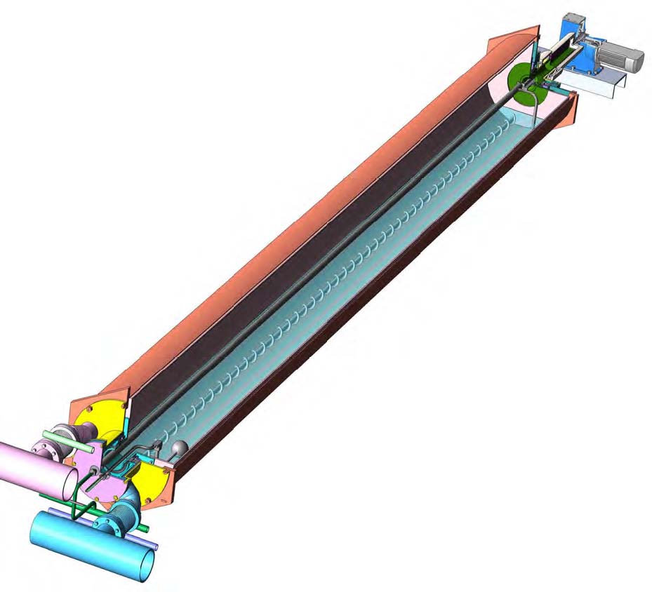
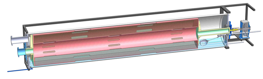
The transition from a sloping glass bulb to a metal horizontal film evaporation drum allows continuous cleaning of the heating surface from deposits below the liquid level. To do this, you can use a heavy rod with a screw winding, which ensures not only the removal of deposits from the surface, but also their transportation to the place of unloading due to the screw properties of the winding when the rod rotates when its axial movement is impossible. The Figure shows a longitudinal section of a steam-heated film evaporation drum and shows a coiled rod for cleaning the heating surface and transporting the sludge to the discharge point.
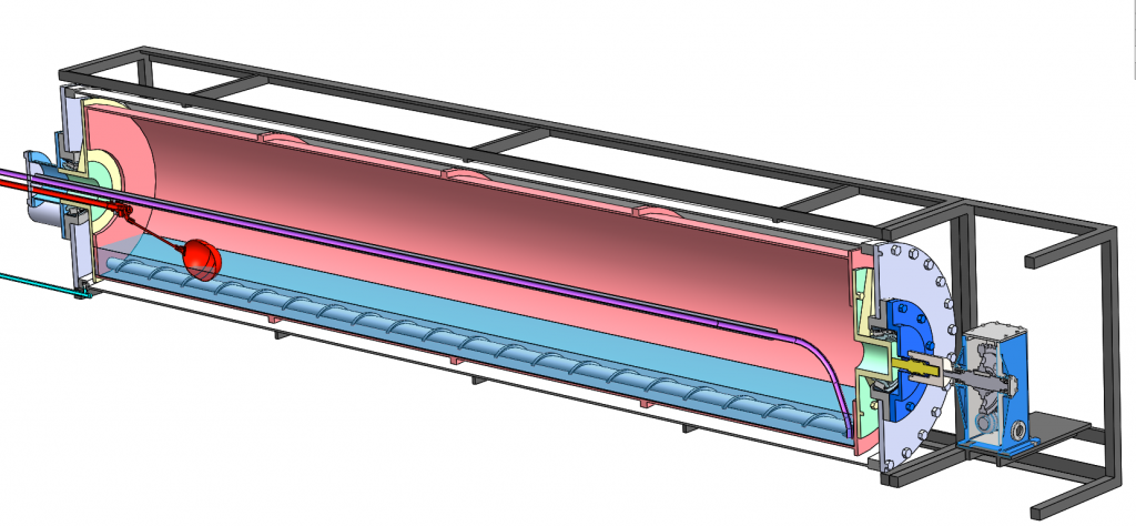
Steam-heated film evaporation drum with rolling rod screw design for cleaning the heating surface and transporting the sludge to the discharge point
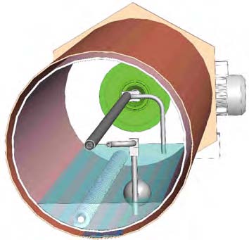
It is possible that such a design of the sediment cleaning device can cause distrust in its performance, therefore, the following figure shows a longitudinal section of the film evaporation drum with a variant of the scraper device for cleaning the heating surface and transporting the sludge to the unloading point. But this option will require significantly more torque to ensure the rotation of the drum.
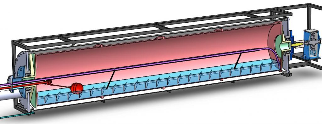
Steam-heated film evaporation drum with a scraper option for cleaning the heating surface and transporting the sludge to the discharge point
From the point of view of heat engineering, this is a conventional heat exchanger with evaporation-condensation heat transfer through the wall and with the presence of moving parts, which can be attributed to disadvantages. However, it is the rotation of the drum that makes it possible to ensure constant cleaning of the heating surface from salt deposits, so this complication can be considered justified. The film nature of evaporation from the surface makes it possible to get rid of or minimize droplet-aerosol entrainment, which is extremely important when concentrating LRW to obtain clean water free from radiation control.
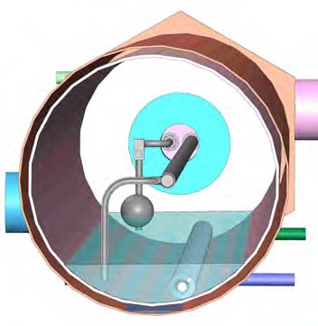
And yet, when evaporating radioactive water (for example, from special laundry rooms) containing surface-active substances (surfactants), foaming is unlikely to be avoided. When bursting, soap bubbles create a cloud of aerosols in the steam and pollute it. Therefore, for additional steam purification in LRW concentration evaporators, it is proposed to use packing-type mass-exchange apparatuses of a drum design. The simplest single-stage packed absorber is shown in Figure
Single Stage Packed Drum Absorber
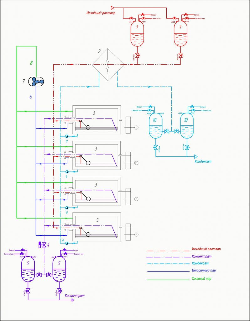
The principle of operation of this absorber is quite simple — the steam contaminated with aerosols, passing through a layer of nozzles (for example, spiral prismatic nozzles) is cleaned, transferring pollution to clean water (phlegm), which flows through the mass transfer apparatus. The aerosol-contaminated phlegm then goes to the same evaporator for purification. To improve the quality of steam cleaning, this absorber can be made multi-stage, as shown in a simplified diagram of an evaporator plant operating on the principle of steam recompression in a Roots pump (Figure). The relative heat engineering parameters of the evaporator plant are also given in terms of one linear meter of a steel evaporator drum with a diameter of 500 mm and a wall thickness of 6 mm.
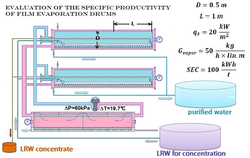
A simplified diagram of an evaporator plant operating on the technology of steam recompression in the Roots pump with multi-stage cleaning of steam from aerosols
This scheme is quite simple and clear: the secondary steam from the evaporator drums (indicated in blue) enters the Roots pump, where it is compressed and the temperature rises (pink). After being cleaned in a multi-stage drum packed absorber, it enters the heating jacket of the evaporator drums, where it condenses and is discharged into a clean water tank. Liquid radioactive waste enters the evaporator drums, compensating for the loss of water from the drum carried away by the secondary steam. When a predetermined solution concentration of 700-800 g/l is reached, the concentrate is periodically discharged into a vacuum container using a siphon effect.
New technology for processing liquid radioactive waste
The LRW conditioning system includes a modular evaporation plant using thin-film evaporation technology and a cementing plant for the resulting concentrate.
Water is removed by evaporation from the inner heated surface of a rotating film evaporation drum (FED) heated by heating steam, which is under vacuum. The flow of secondary steam before entering the compressor is sent for purification from radionuclides in a horizontal heat-and-mass exchange apparatus. The steam cleaned and compressed in the compressor is used as heating steam in the film evaporation drums. Steam condensate can be reused or discharged into an open water network. The LRW concentrate is periodically pumped out into a tank under vacuum, and after filling it, the concentrate is sent for cementing.
The technology provides low-temperature processing and production of condensate close to the drinking water standard. The equipment can be designed in both mobile and stationary configurations. This technology would allow multiple units to be deployed in a parallel configuration to meet both capacity and concentration requirements.
The configuration of the liquid radioactive waste (LRW) processing system at the stages of concentration and conditioning in cement compound packages is considered. The combination of diversity factors of the radionuclide and chemical composition of LRW prompted the search for the best way to handle liquid waste, including the technology of their processing to the stage of a cement compound.
3D model of the FACILITY FOR CONCENTRATION AND CONDITIONING OF LIQUID RADIOACTIVE WASTE CAN BE DOWNLOADED FROM THE LINK
https://grabcad.com/library/facility-for-concentration-and-conditioning-of-liquid-radioactive-waste-1

The main tasks of the proposed technology to be solved are
— a sharp decrease in the volume of LRW;
— reduction of wastewater activity;
— improving cost efficiency;
— creation of effective packages of the cement compound, providing protection against migration of radionuclides for millennia.
The main features of the technology are
— non-reagent evaporation of LRW in film evaporation drums (FTE) with the use of vapor recompression technology
— continuous mechanical cleaning of heating surfaces in BPI to prevent the formation of salt deposits
— purification of secondary steam from radioactive aerosols until an activity level is reached that allows its reuse or discharge into an open water network
— modular design of evaporator and tank equipment, allowing the use of unification for the transition to mass production in order to reduce its cost
— the use of a combination of layers of glass and bentonite clay as an external barrier for packages with a cement compound, which ensures the long-term barrier during burial at final isolation points.
All clarifications on the technology of concentration and conditioning of liquid radioactive waste can be obtained by e-mail uzikov62@mail.ru
Plant for concentration and conditioning of liquid radioactive waste
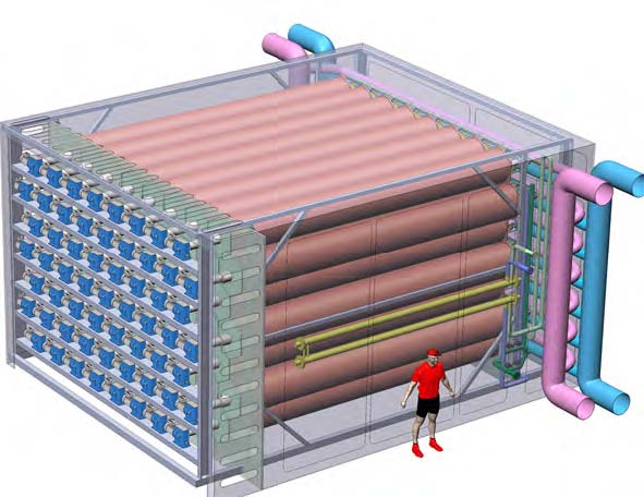
The modular structure of radwaste concentration plants, including film evaporation drums and horizontal packed heat and mass transfer apparatuses, makes it possible to use unified and relatively inexpensive equipment to create LRW treatment plants of a given capacity. At the same time, the dimensions of this equipment allow transportation by conventional transport, and installation and dismantling is carried out using standard transport and technological equipment.
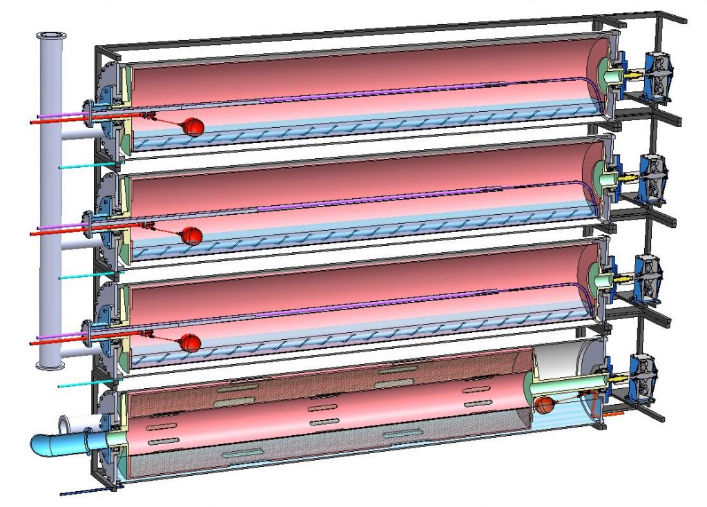
Figure — Unit for LRW evaporation and secondary steam treatment
The rotation of the film evaporation drums and the mass transfer apparatus at the optimum speed is provided by motor reducers. The same figure shows a tank with clean water (phlegm).
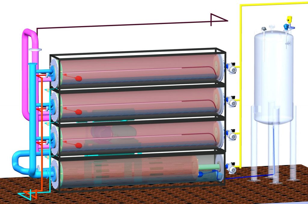
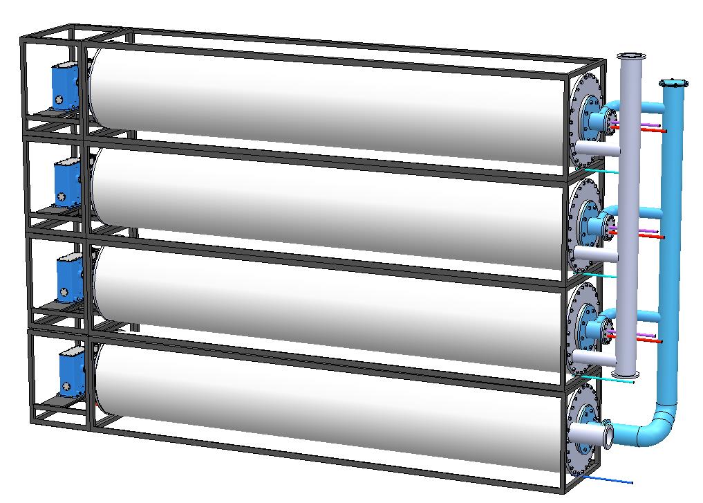
Figure — Reflux supply tank and drives for rotation of film evaporation drums and mass transfer apparatus
To ensure the continuity of operation of the plant, the tanks of the initial solution, purified distillate and LRW concentrate are made in the form of identical modules of two tanks, loading and unloading from which is carried out using a vacuum line (yellow pipe at the top) and a compressed air line (green pipe at the top). Using solenoid valves, these lines are alternately switched, either filling or emptying the corresponding container.
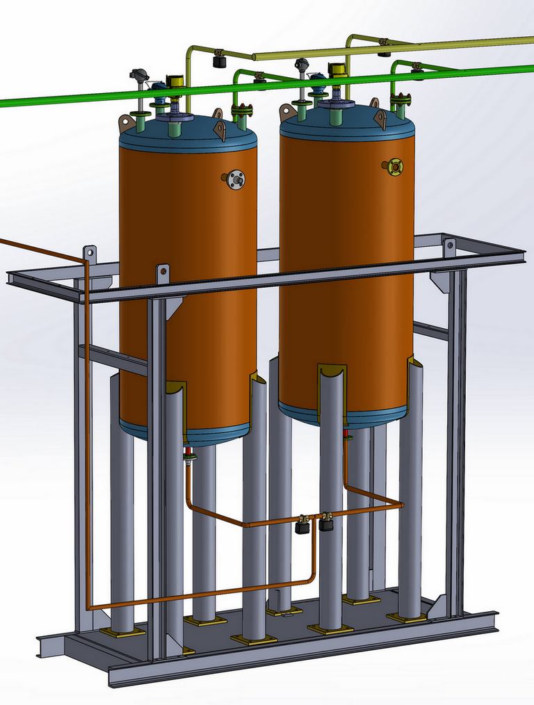
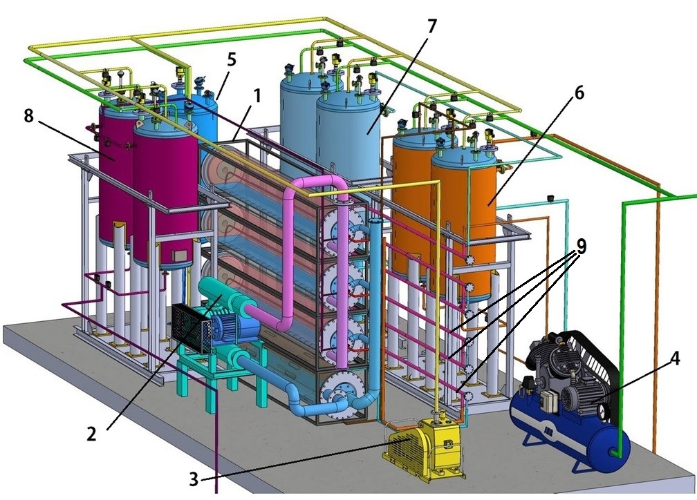
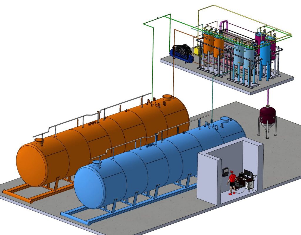
Figure — Installation of LRW concentration with a capacity of 500 l/h
Before starting the LRW concentration plant, liquid radioactive waste is accumulated in a large tank. In the Figure, the plant is shown concentrated in conjunction with an LRW storage tank (volume 100 m3) — orange, a purified distillate tank (volume 100 m3) — blue, and a concentrate collection tank (volume 3 m3) — dark cherry color.
As a possible option for the medium and low level LRW processing plant, the resulting LRW concentrate can be collected not in a tank, but fed directly to the cementing line (Figure).
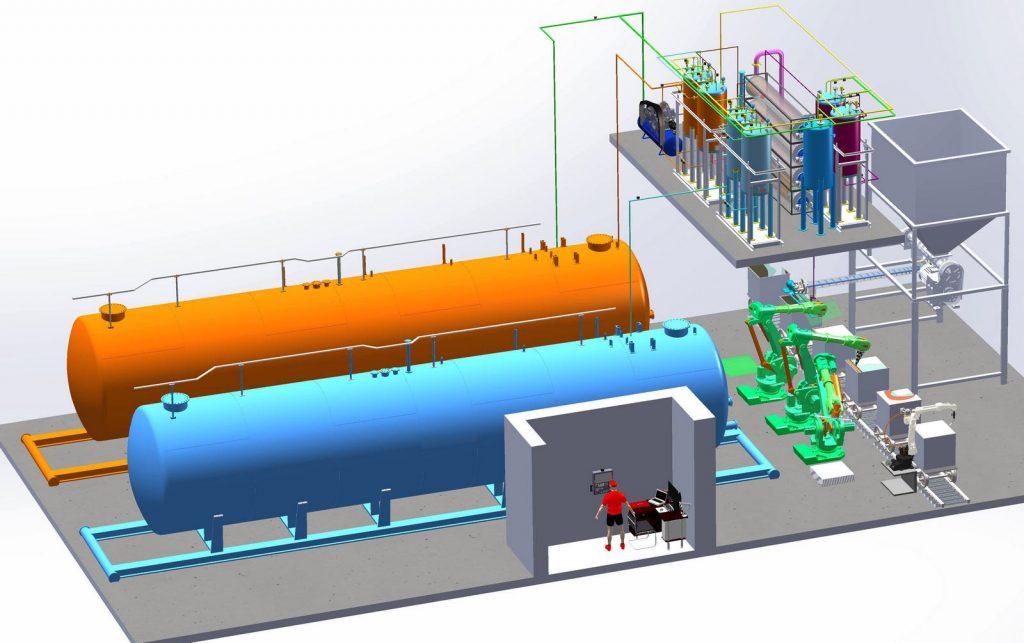
Figure — LRW concentration plant with a capacity of 500 l/h in conjunction with a concentrate cementing line
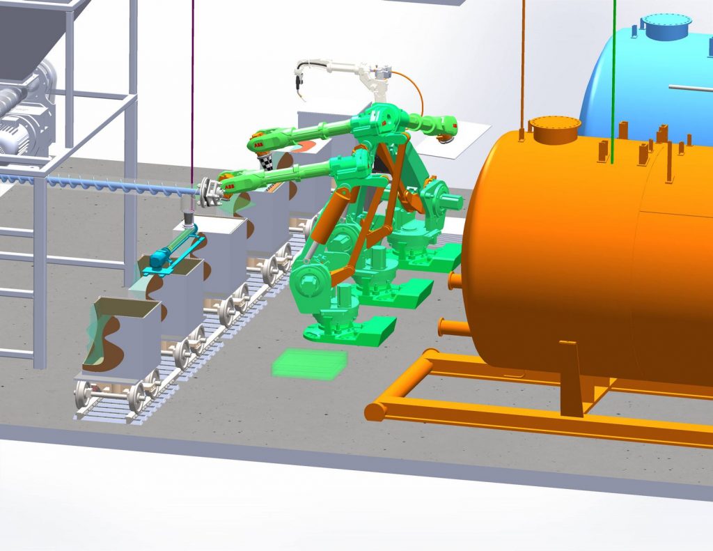
The LRW concentrate cementing line is a conveyor of packages moved on trolleys, in which the following is sequentially produced:
• filling with cement compound;
• covering the surface of the compound with sheet glass;
• covering the surface of sheet glass with bentonite clay;
• covering the steel box of the package with a steel sheet;
• sealing of steel packaging by welding.
Due to high dose loads, it is proposed to use industrial robots to carry out technological operations to create packages.
Packaging for optimal use of the volume of the burial ground has a rectangular shape. The body of the package is formed by a steel thin-walled box, as well as layers of bentonite clay and sheet glass lining the inner surface of the box.
Cementing according to a given recipe of the LRW concentrate with the production of a compound can be carried out using a replaceable continuous-action quick-detachable mixer, into which the concentrate is simultaneously drained and the cement mixture is dosed by the screw.
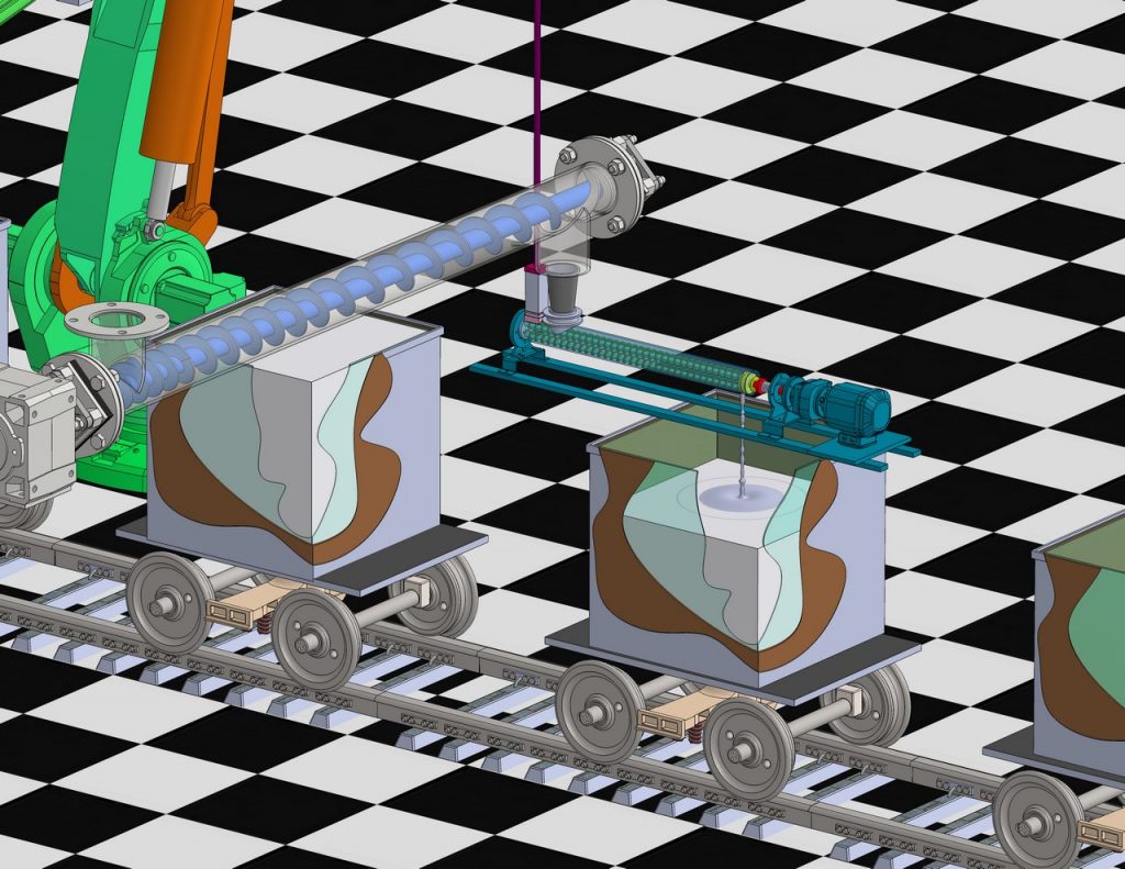
Figure — Installation for the preparation of a cement compound and filling the package
The design of the mixer ensures the movement of the prepared cement compound to the place of unloading into the package. The eccentric arrangement of the rotating structure with 3 rods surrounded by springs makes it impossible for the rods and springs to form a crust. In addition, the winding of the springs creates a screw effect to move the compound towards the discharge, while creating pressure to force the finished cement slurry through the outlet.
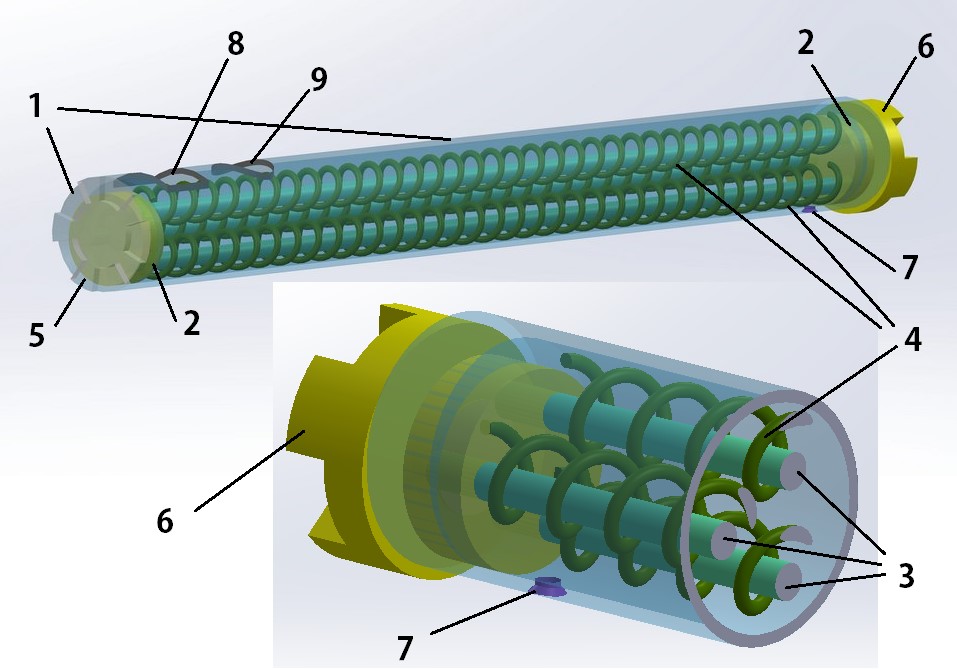
Figure — Design of a replaceable mixer
The dimensions of the package are such that the used replacement mixer fits in the box and is subsequently buried in it together with the cement mortar with which the package is filled.
A limited amount of spent sorbents, including monoexchange resins, can also be fed into the mixer for subsequent immobilization in the compound.
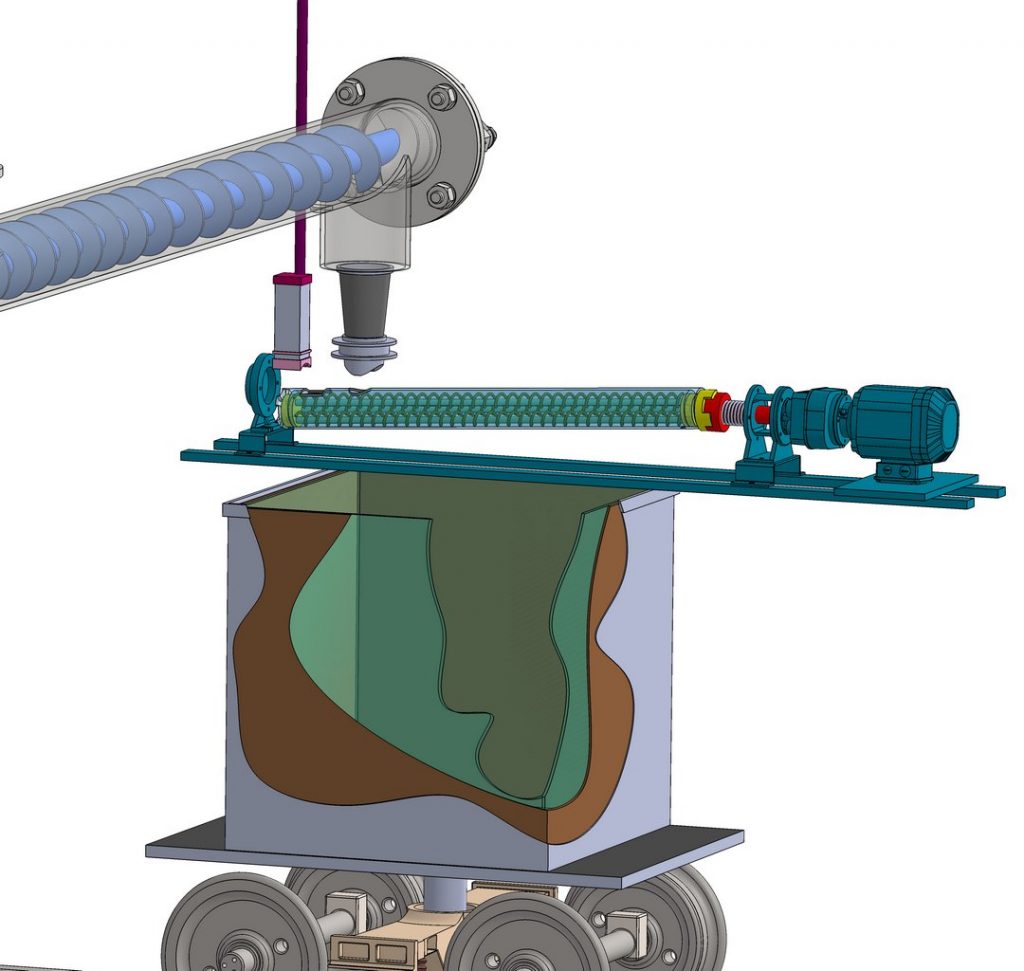
Figure — Removing the replacement faucet
When the package is buried, corrosion will destroy the steel envelope relatively quickly, but the combination of glass and bentonite layers will provide long-term protection against radionuclide migration even after numerous cracks in the glass have formed, which will be filled with bentonite.
Thus, a simple and relatively inexpensive package can help solve the problem of accumulation of radioactive waste of low and medium activity.
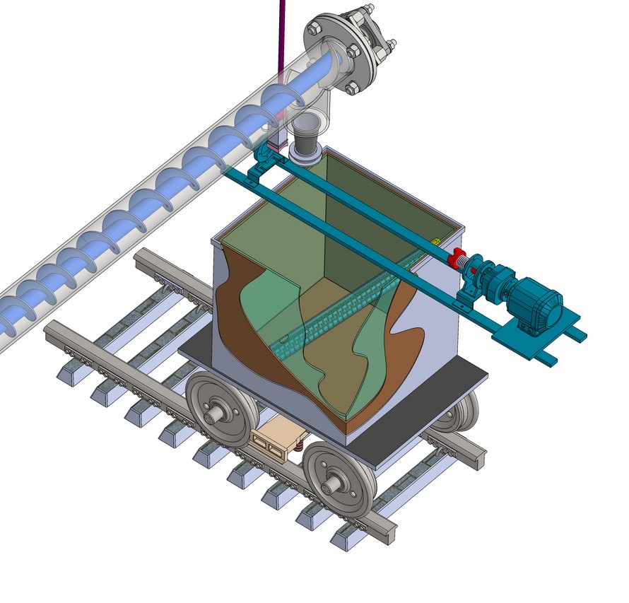
Figure — Placement of the used replacement mixer in the package before filling with cement compound
uzikof@gmail.com
uzikov62@mail.ru
Address
Bratskaya st., 27 apt. 61 Dimitrovgrad, Ulyanovsk region, Russia, 433515
Call Us
+7 917 622 40 47